Description
- Hign-concerned Chemical: None
- Electronic: No
- Material Type: Plastic+Metal+Rubber
- Item Weight: 301g
- External Testing Certification: ce
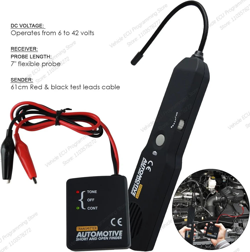
- Voltage: 6V-42V
- Power: 0
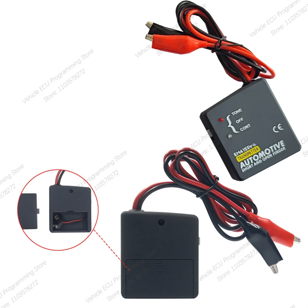
- Model Name: EM415
- Software Version: ~
- Hardware Version: Circuit tester
- Item Type: Other
- Origin: Mainland China
- Certification: CE


Dear customers, please take a look:
① Our engineers have tested this product, it works 100%.
② If you receive a product that cannot be used, please contact me for a solution!
③ If you receive damaged products, please contact me for compensation negotiation!
④ Please read the product instructions before use and follow the usage rules. Thank you!
⑤ If you still encounter problems that you can't solve by yourself, please contact us, professional after-sales service!
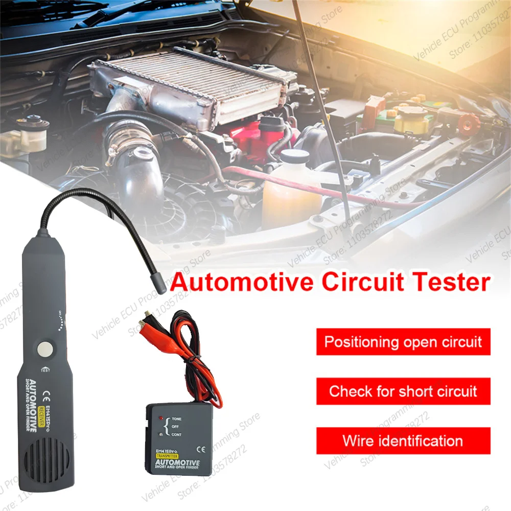
Description :
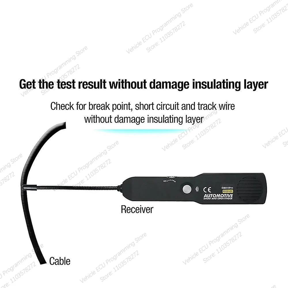
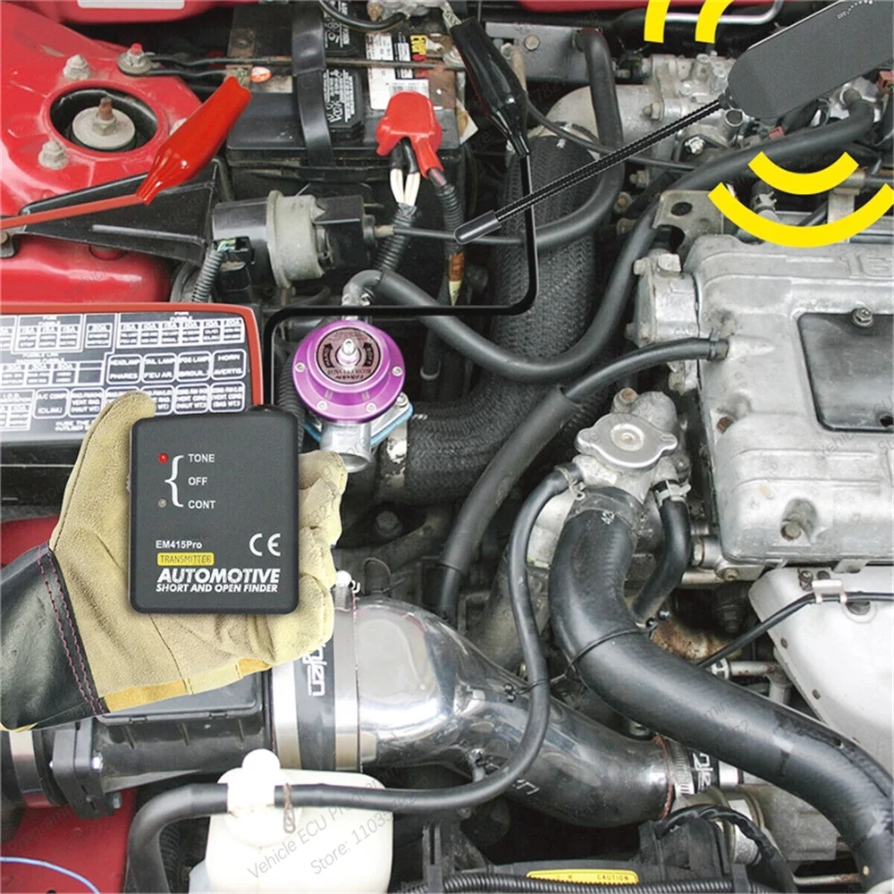
EM415 detects and alerts you immediately where a circuit is open.You can quickly and easily Locate short circuits,open connections,broken wires,current leaks and even trace wires.You can also find intermittent circuit problems by flexing wires or connectors and listening for a change in the receiver tone Allowing you general tracing or pinpointing the problem location.It also shows you the direction to the short with its direction indicator,eliminating the guesswork. This professional tool will work on all kinds of circuits with voltages between 6 and 42 volt DC.such as those found in automobiles, trucks, tractors, boats, RVs, etc…With its wide working voltage range.
Specifics:
Power:Two 9V batteries (Not Included In Package)
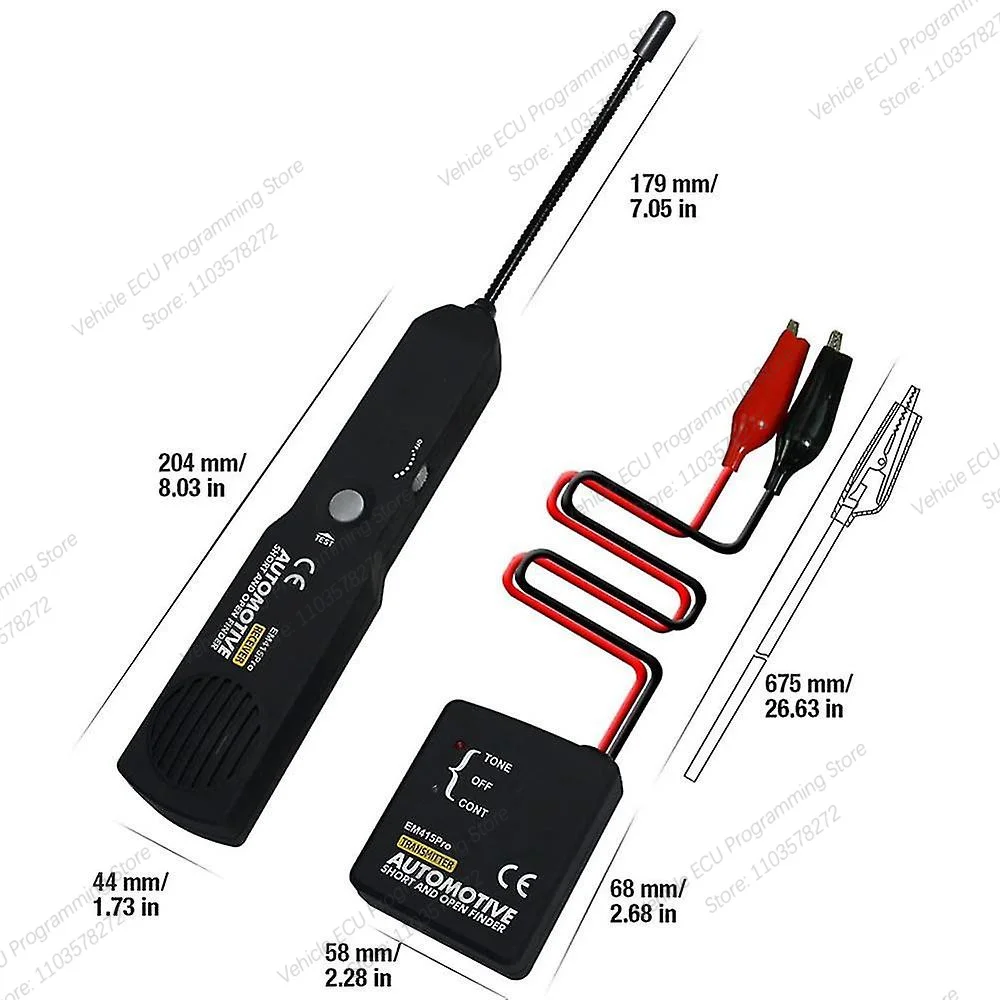
Item Width:4 cm
Material Type:coiled steel
Item Height:15 inch
Item Type:Electrical Testers & Test Leads
Item Length:17 cm
Special Features:short cable finder
Feature:
▶ Judge continuty of the cables or wires.
▶ Track the cables or wires, and diagnose the break point
▶ Receive the tone signal on the cables or wires(telephone line)
▶ Indentify the state in the working telephone line(clear, ring, busy)
▶ Send a single solid tone or a dual alternating tone to the object cables or wires.
Caution:
1.Only for use on DC voltage,don't connect to circuit exceeding42 volts DC under any circumstances.
2. Do not use on AC voltage.
3. Do not use on any circuit directly or indirectly connected toAC lines or any other AC power source.
4. Do not use with any component or circuits of the ignition system.
5.Before using this device, check the vehicle's electrical wiring and disconnect any part or system sensitive to voltage andcurrent pulses such as air bags, electronic control modulesetc.
6.After you finish checking vehicle, make sure you havecorrectly restored all the connections which youdisconnected.
7.Always follow the instructions and procedures indicated in thevehicle's service manual before attempting to disconnect anypart or subsystem of the electrical circuit.
Exceeding the limits listed above when using this apparatus, ornot observing the precautions listed above can expose you tophysical injury and permanently damage your instrument andparts and circuits of the vehicle under test.
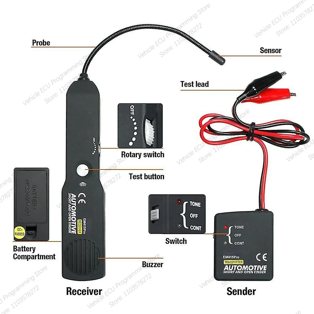
How to use the probe:
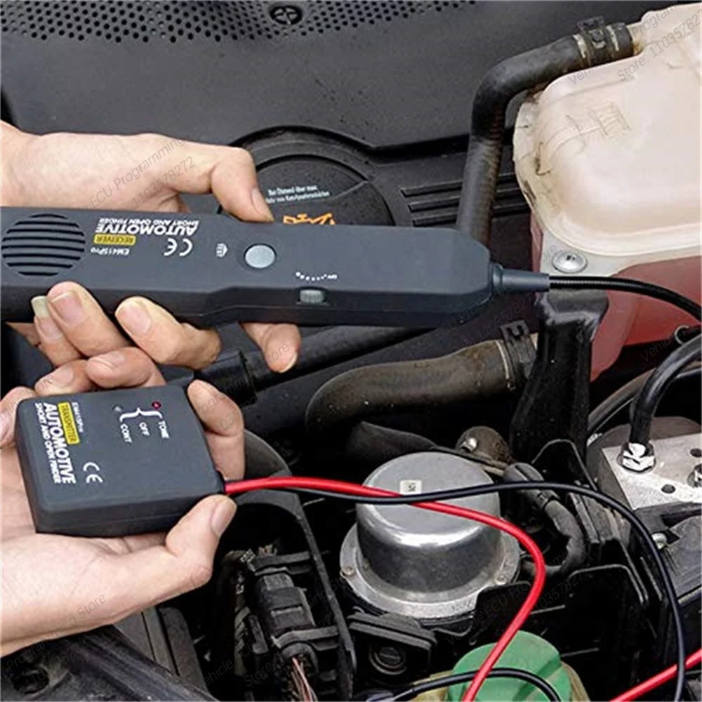
The probe of the Receiver is built of coiled steel and may bebent as needed. in order to reach wires in congested or difficultareas. Depending on the circuit characteristic and sensitivitysettings, the probe will pickup the signal from the wire in a rangeof positions. However, for the best possible range the Receiver'sprobe tip (black cap) should be positioned perpendicular(at 90°)to the wire being traced and either above or below it.
Setting Sensitivity level:
To turn on Receiver or increase its sensitivity, turn the rotaryswitch of Receiver clockwise. To turn off Receiver or decreaseits sensitivity, turn the rotary switch anticlockwise.
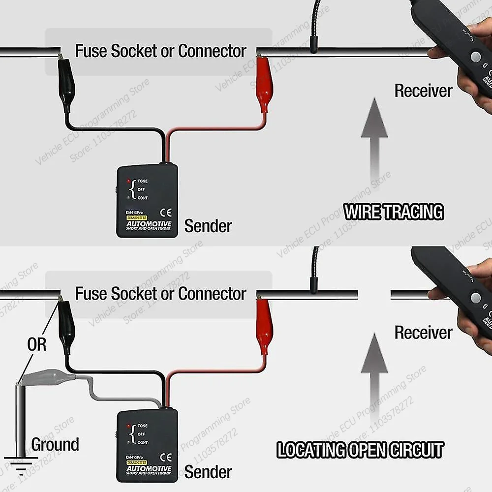
Wire tracking:
Note: Observe the limits and safety precautions at all times,
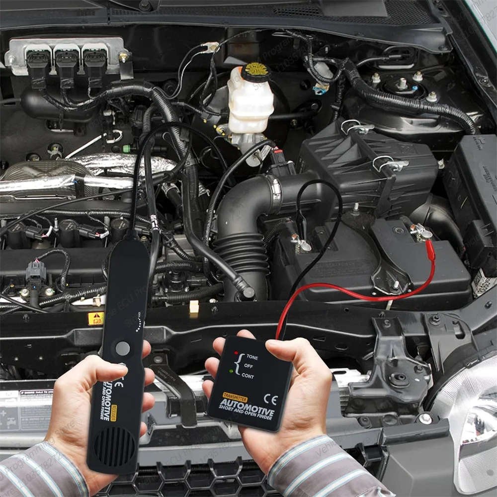
1. Set the switch of Sender to "TONE", the red LED of Senderlights. lf the red LED doesn't light, please check the battery.
2. Switch Receiver on, set the rotary switch in middle position.Press and hold TEST button, meanwhile move the sensorclose to the test lead of Sender. Receiver receives the signaland give audio signal. lf so, it means that the unit workscorrectly.
3. Connect the black test lead to the circuit% positive supply(or to the negative for vehicles with positive supply connectedto chassis).
Connect the red test lead to the wire to be traced. A fusesocket (in place of the blown fuse), connector,etc.isconvenient place.
4.Set the rotary switch in middle position.Press and hold TESTbutton, meanwhile move the probe as close as possible tothe wire to be traced. The Receiver's sensor should bepositioned perpendicular(at 90°) to the wire being traced and
either above or below it.
5.Receiver gives audio signal. Trace the wire by following theaudio signal of Receiver. lf you move the probe away fromthe wire, the audio signal will decrease and then disappears.
6. lf it is difficult or impossible to get the Receiver to pick-up anysignal, please increase the sensitivity and try again. For thesuspectable place, check it twice.
7.When you finish tracing, disconnect the test leadsconnections,set the Sender's switch in OFF position. LooseTEST button.
Check for Short circuits:
Note: Observe the limits and safety precautions at all times
1.Disconnect the power to the wire to be checked and removeall the loads from this wire (for example: remove the lampfrom the wire).
2. Set the switch of Sender to "CONT" position. Connect thetest leads to a couple of wires which are to be checked.
3.When the resistance is less than 10k ohm, the green LED of"CONT" will light。 With all the loads having been removedthe green LED's lighting indicates that the couple of wiresare in short circuit .
Locating Open circuit:
Note:Observe the limits and safety precautions at all times
1.Set the switch of Sender to "TONE" the red LED of Senderlights. lf the red LED doesn't light please check the battery.
2.Switch the Receiver on, set the rotary switch in middleposition.Press and hold TEST button, meanwhile move thesensor close to the test lead of Sender. The Receiverreceives the signal and give audio signal. lf so, it meansthat the unit works correctly.
3.Connect the black test lead to the circuit's positive supply(or to the negative for vehicles with positive supply connected to chassis). Connect the red test lead to the wireto be checked.Afuse socket (in place of the blown fuse).connector, etc.is convenient place.
4.Switch Receiver on and set its rotary switch in middle positionPress and hold "TEST" button and slowly sweep the wire withthe probe, ensuring the probe is perpendicular and above orbelow the wire being checked and as close as possible to it.
5. Follow the wire or check it at different points, starting from theSender and moving towards the load (accessory light. etc)observing the positioning of the probe as indicated above.
6.Continue this procedure while the audio siqnal indicates theintegrity of the circuit, lf audio signal stops, it indicates that theprobe has passed beyond the open, break or bad connectionin the circuit.
7. lf it is difficult or impossible to get the Receiver to pick-up anysignal, please increase the sensitivity and try again.
8. Double check by positioning the probe before and after thesuspected place.lf the open circuit point has been found, theaudio indicator will show circuit integrity on the side, and noton other.At this point, where the audio signal stops, you havefound the open circuit.
9. When you finish locating, disconnect the test leads’connections, set the Sender's switch in OFF position.LooseTEST button.
Wire identification:
Note: Observe the limits and safety precautions at all times
1. Set the switch of Sender to "TONE", the red led of Senderlights. lf the red LED doesn't light, please check the battery.
2. Switch the Receiver on, set the rotary switch in middle positionPress and hold TEST button, meanwhile move the sensorclose to the test lead of Sender, The Receiver receives thesignal and give audio signal. if so, it means that the unitworks correctly.
3. Connect the black test lead to the circuits? positive supply (orto the negative for vehicles with positive supply connected tochassis). Connect the red test lead to the wire to be identified.A fuse socket (in place of the blown fuse), connector, etc. isconvenient place.
4.Sweep all the suspectable wires until the audio signal is at itsmaximum. the wire which makes Receiver give the loudestaudio signal is the wire to be identified.In the case of tightly packed wires (bundles, conduit, etc.), itmay be necessary to spread these apart to facilitate theidentification process of a particular wire .
5.When you finish identification,disconnect the test leads'connections, set the Sender's switch in OFF position. LooseTEST button.
Battery Replacement:
1.Sender Battery replacement:Remove the screw on the back case, remove the back casereplace the exhausted battery with a new one of 9V(6F22)Rejoin the back case and install the screw.
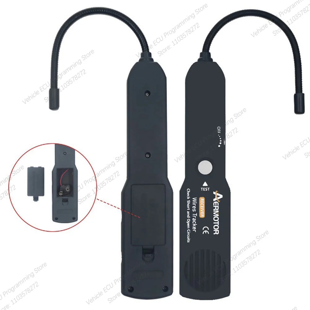
2.Receiver Battery replacement:Remove the screw on the battery compartment, remove thebattery cover, replace the exhausted battery with a new oneof 9V(6F22).Rejoin the cover and install the screw.
Package List (4PCS):
1pc x Receiver
1pc x Sender
1pc x Instructions
1pc x Nylon bag

Looking forward to your first order!